
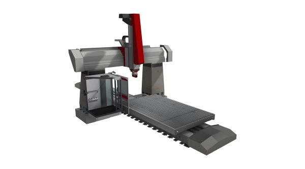
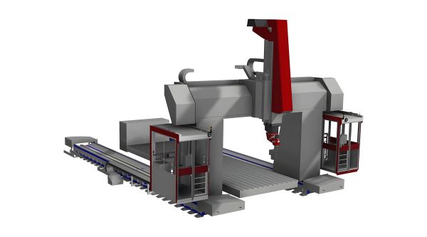
WFC 10/11 (L)
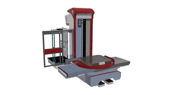
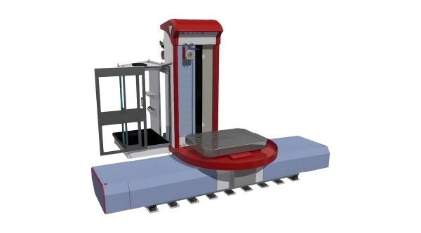
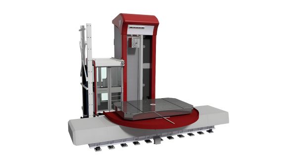
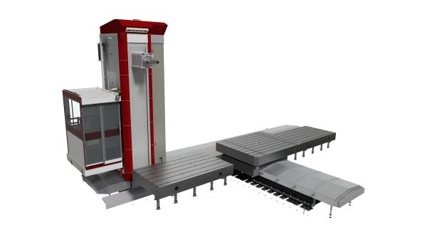
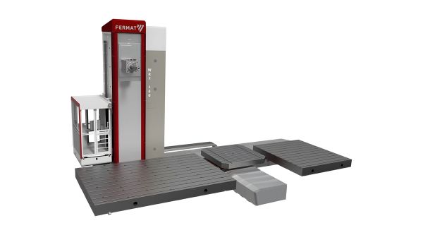
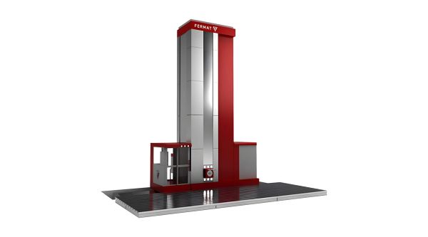
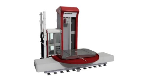
Series · WFC 10/11- Cross-type layout, compact footprint — The column is static and the workpiece moves in both X and Z, fitting a rigid cast-iron machine into a small footprint — suited to shops with limited floor space and to serial production.
- Ø 100/110 mm spindle, 730 mm stroke — Two-stage gearbox and three-belt drive up to 4 000 rpm, with a 250 mm support sleeve supplied as standard.
- Active thermal compensation — The headstock is monitored by four temperature sensors, cooled by an automatic air/oil gearbox circuit, and the control corrects spindle dilation in the Z axis automatically.
- T5 rotary table, 5 000 kg — Cross-roller bearing, master–slave B-axis drive through two CNC-controlled servomotors and four hydraulic clamping brakes.
Overview
The WFC 10 is a cross-type horizontal boring and milling machine for single-setup work on workpieces up to 5 tonnes, built for shops with limited floor space and suited to serial production. The column stays fixed while the workpiece travels in both axes, so the machine keeps the rigidity of a fully cast-iron structure — CNC rotary table included, driven by two servomotors — in a smaller footprint than a comparable floor-type. Headstock, column, beds, tables and heads are all designed and built by FERMAT in-house, which keeps accuracy repeatable and spares on the shelf.
Explore WFC 10/11 (L)
Full technical specifications. Toggle between metric and imperial units.
| Parameter | Units | WFC 10/11 | WFC 10 L |
|---|---|---|---|
| Spindle diameter | mm | 100/110 | |
| Spindle taper | — | SK 50 (DIN, MAS 45°, ANSI) | |
| Spindle speed (max.) | rpm | 4000 (opt. 5000) | |
| Main Power Heidenhain or SIEMENS CNC (S1/S6) | kW | 31/46,5 | |
| Max. Torque Heidenhain or SIEMENS CNC (S1/S6) | Nm | 1416/2124 | |
| Main Power FANUC CNC (S1/S3) | kW | 30/37 | |
| Max. Torque FANUC CNC (S1/S3) | Nm | 1370/1692 | |
| X-axis Cross Travel of Table | mm | 1250/2000 | |
| Y-axis Vertical Travel of Headstock | mm | 1250/1700/2000 | |
| Z-axis Longitudinal Travel of Table | mm | 1250 | 1500 |
| W-axis Spindle Travel | mm | 730 | |
| Rapid Feed X, Y, Z | mm/min | 12000/12000/8500 | 30000 |
| Rapid Feed W | mm/min | 8000 | 12000 |
| Rapid Feed B | rpm | 2 (5 optional) | 10 |
| Max. Table Load | kg | 5000 | |
| Table Size | mm | 1000×1120 / 1250×1400 / 1250×1800 / 1400×1600 / 1400×1800 | |
Customize WFC 10/11 (L)
Pick a category to see compatible accessories. Click any accessory to open its detail window.
Angle Heads & Facing Heads
Manual or automatic angle heads and facing heads for extended machining capability — UHAmi, UHA, PHA, PHAmi, OHA series and more.
Showing 6 of 6
Technology & Software
Smart technologies, control platforms and multitasking capabilities available on this machine. Click any item for details and the full list of compatible machines.
Smart Technologies
Explore smart technologies3D Kinematic Calibration
Measure and correct the machine's kinematic transformation — restores accuracy to the rotary axes without waiting for service.
Vibration Monitoring
Sensors on the spindle and ram watch vibration levels in real time — protecting the machine, the tool and the surface finish.
Adaptive Feed Control
The CNC adjusts feed rate in real time based on spindle load — shorter cycle times in light cuts, tool protection in heavy ones.
Machine Collision Monitoring
The control knows the shape of the machine and stops it before it hits itself — in automatic mode and while jogging by hand.
Spindle Temperature Compensation
Thermal sensors track spindle growth and the CNC compensates automatically — stable accuracy from the first part of the shift to the last.
Multitasking
Explore multitaskingInterpolation Turning
The spindle interpolates X and Y axes in a circular path to turn features anywhere on the workpiece — without rotating the part.
Facing Head Turning
A facing head with CNC U-axis turns external and internal diameters, faces and tapers — contour turning directly from the spindle.
Software & Control
Compare control systemsEASYCRAFT
FERMAT's own conversational control — guided workshop programming of boring and milling cycles without G-code.
FANUC
Robust FANUC CNC in three tiers — FERMAT FANUC, 30i-B Plus and 31i-B Plus — for maximum reliability and worldwide service.
HEIDENHAIN
Premium HEIDENHAIN Klartext controls — TNC 640, TNC7 and TNC7 Basic — for die & mould and high-precision contouring.
SIEMENS SINUMERIK ONE
The digital-native SINUMERIK ONE — top-end Siemens platform with digital-twin capability.
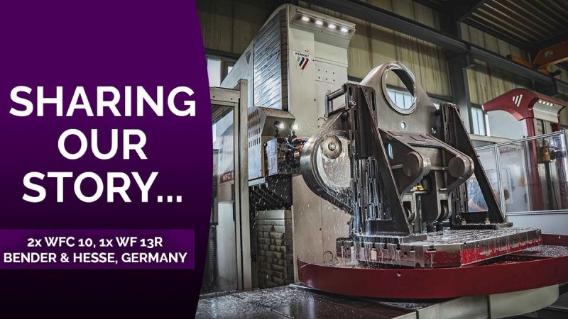
WFC 10/11 (L) Customer Stories
WFC 10/11 (L) FAQ
Procurement and engineering questions we hear about this model.
What makes the WFC 10 a cross-type machine?
How big a workpiece can the WFC 10 take?
What spindle is fitted to the WFC 10?
Why is the boring spindle belt-driven rather than direct-driven?
What is the machine structure made of?
How does the machine hold accuracy as it warms up?
How is the rotary table positioned and clamped?
What tool-change options are available?
Which milling heads fit the WFC 10?
What is the lead time for this machine?
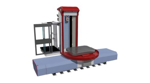
Related Models
Get a tailored proposal for WFC 10/11 (L)
Our engineers spec the exact configuration for your application. We reply within 24 hours.