
 English
  Français
  L'italiano
  Magyar
  Deutch
  Polski
  Română
  Русский
  Čeština
1234 Lista Reja
1234Torno CNC - diámetro de hasta 800 mm
| Nombre del producto | Núm. de inventario | Fabricante | Año de fabricación | Parámetros | ||
|---|---|---|---|---|---|---|
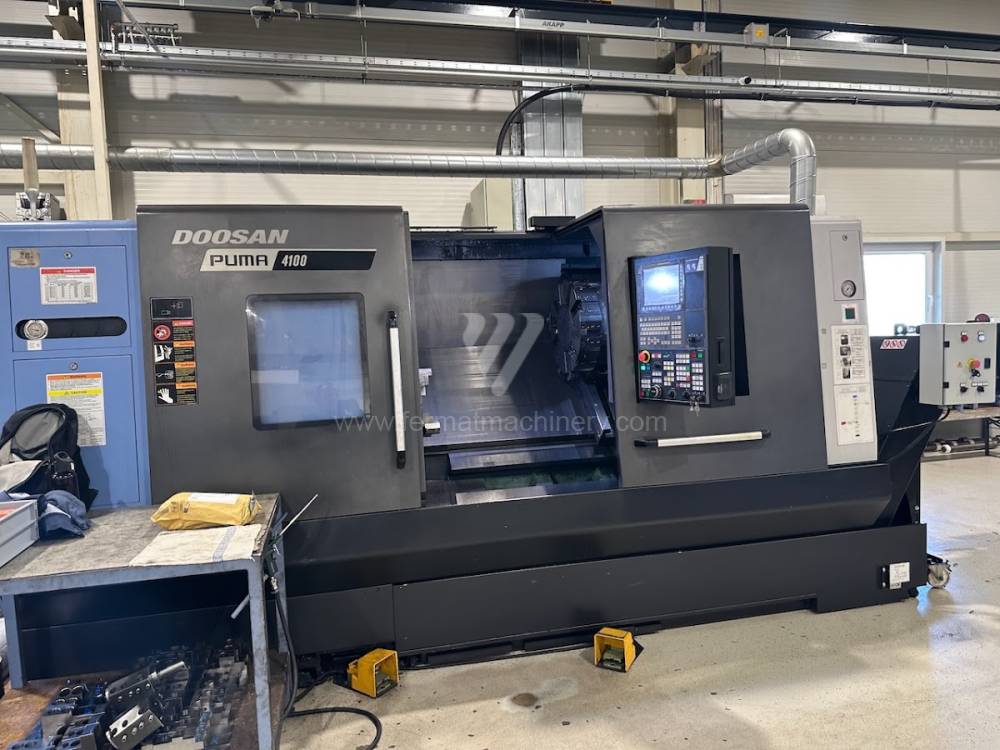 |
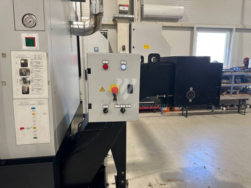
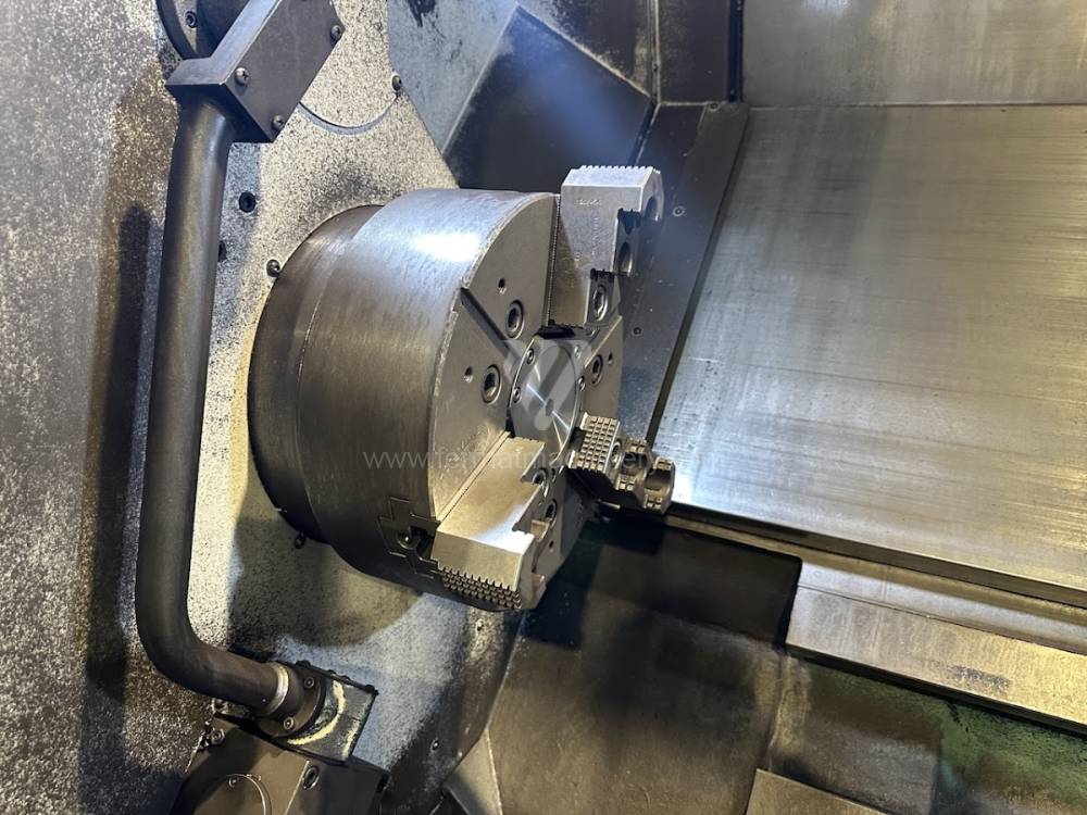
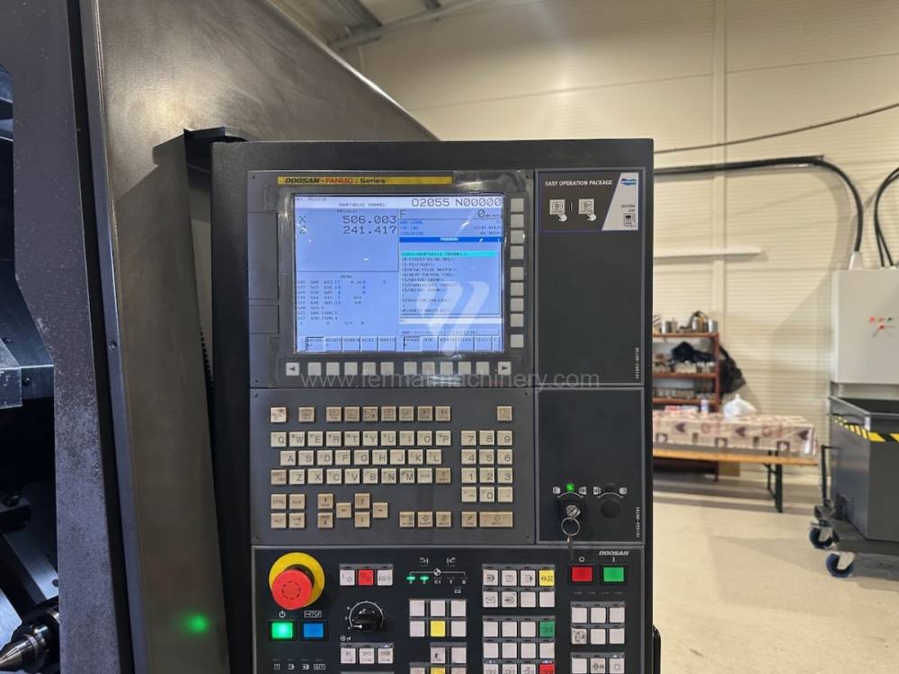
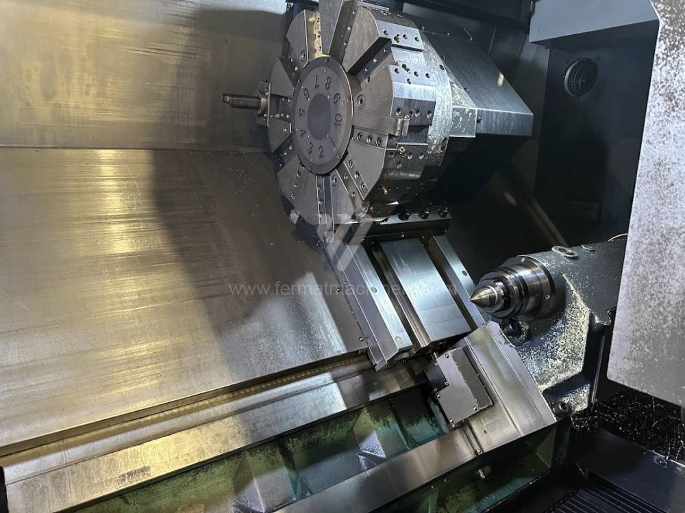
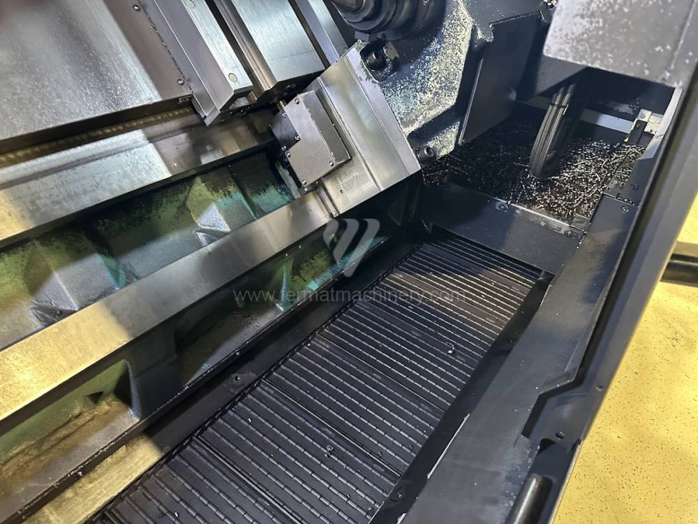
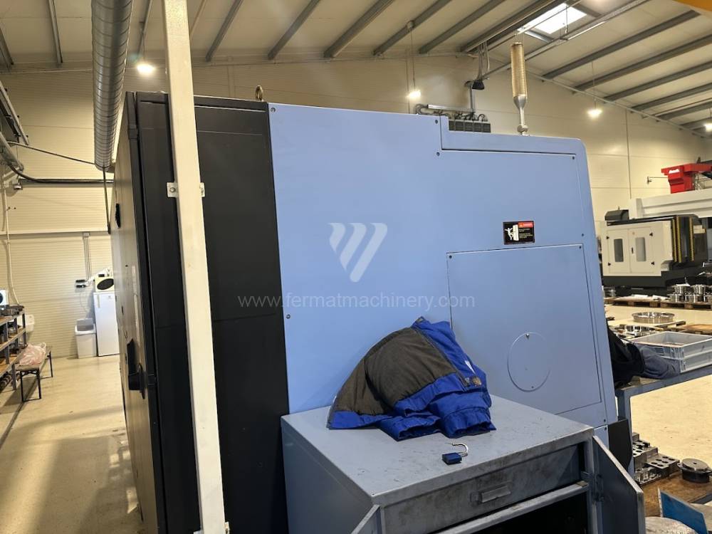
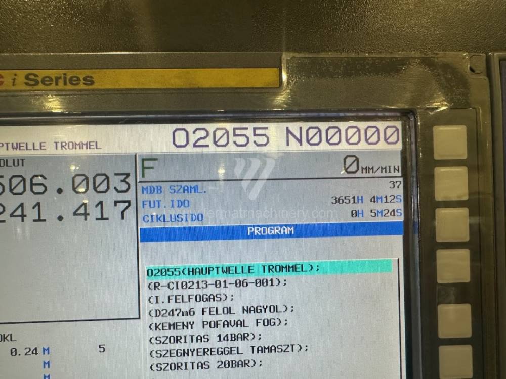
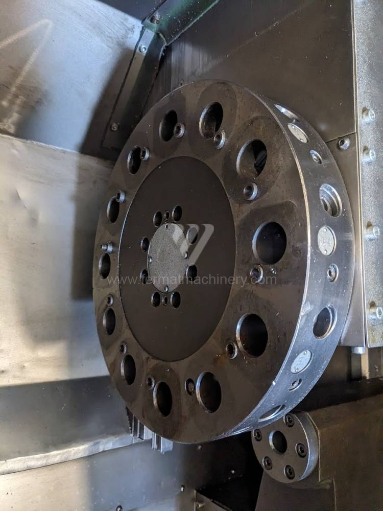
PUMA 4100A |
251162 | Doosan | 2018 | Sistema de control Fanuc: i Series Diámetro de giro: 790 mm Longitud de giro: 1074 mm Lecho inclinado: Sí Perforación del husillo: 102 mm Cabezal de revólver: Sí |
|
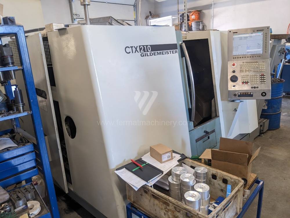 |
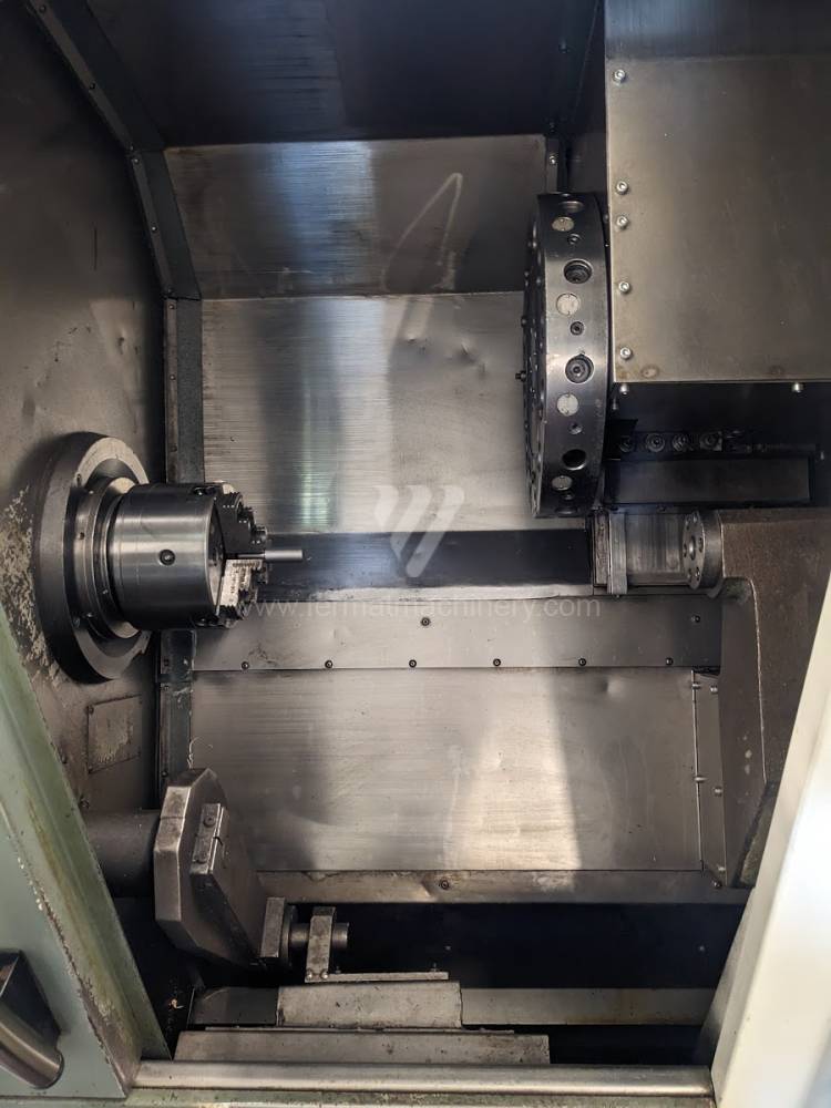
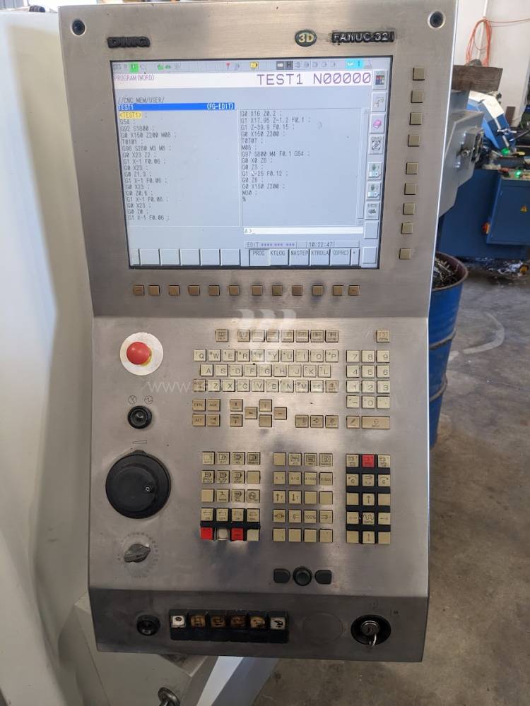
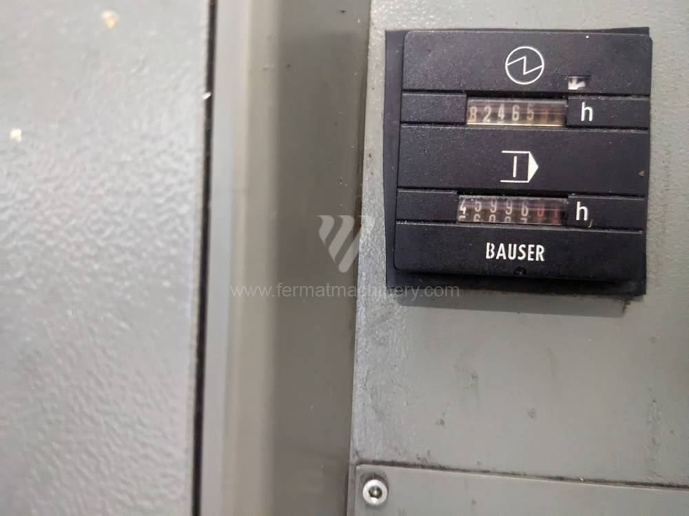
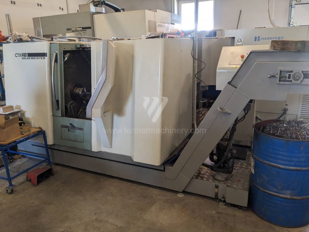
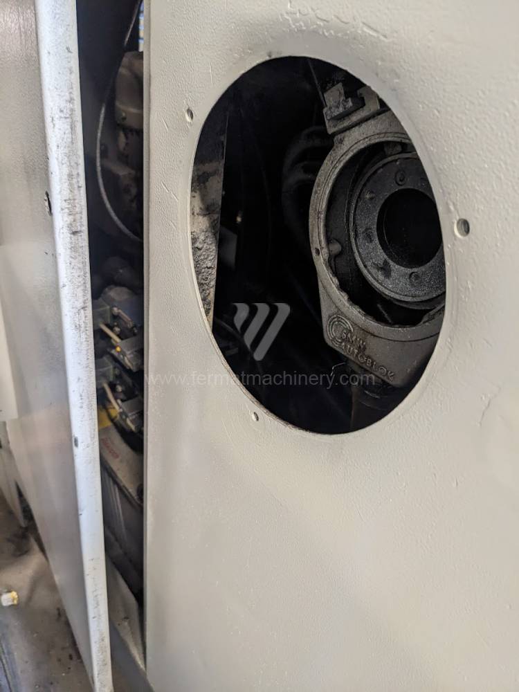
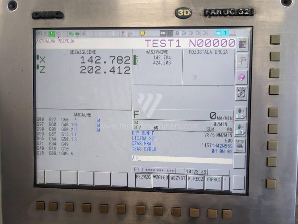
CTX 210 |
231446 | DMG | 2006 | Sistema de control Fanuc: Fanuc 32i Diámetro de giro: 210 mm Longitud de giro: 305 mm Lecho inclinado: Sí Perforación del husillo: 46 mm Cabezal de revólver: Sí |
|
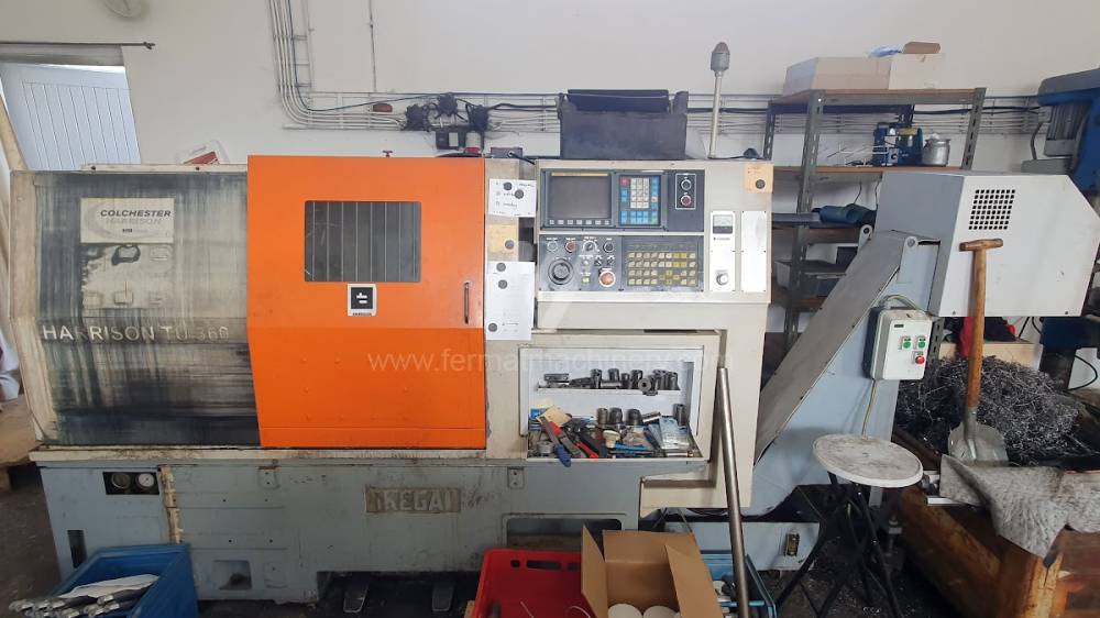 |
Harrison TU 360 |
251748 | Colchester | 1999 | Sistema de control Fanuc: 0TT Diámetro de giro: 360 mm Longitud de giro: 380 mm Lecho inclinado: Sí Perforación del husillo: 40 mm Cabezal de revólver: Sí |
|
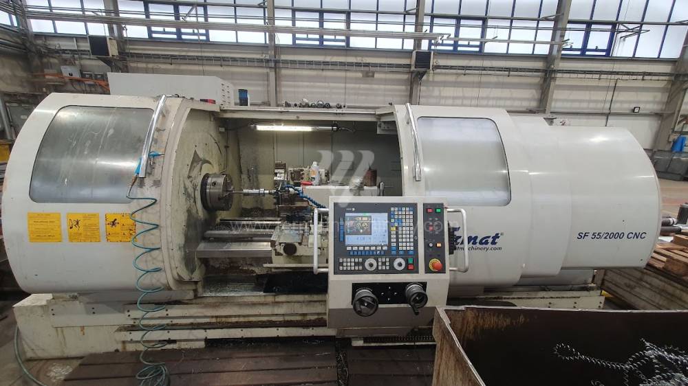 |
SF 55/2000 CNC |
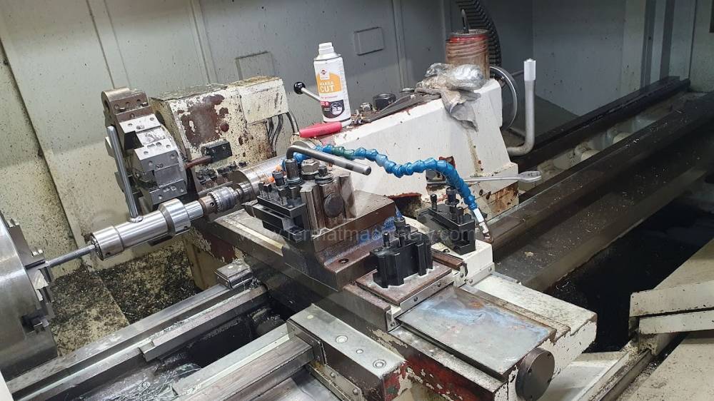
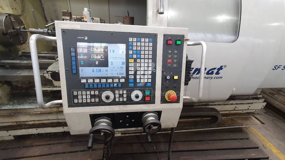
252003 | Fermat | 2011 | Sistema de control Fagor: Diámetro de giro: 790 mm Longitud de giro: 2000 mm Diámetro de giro sobre el lecho: 550 mm Diámetro de giro sobre el soporte: 310 mm Máx. peso pieza mecanizada: 2000 kg |
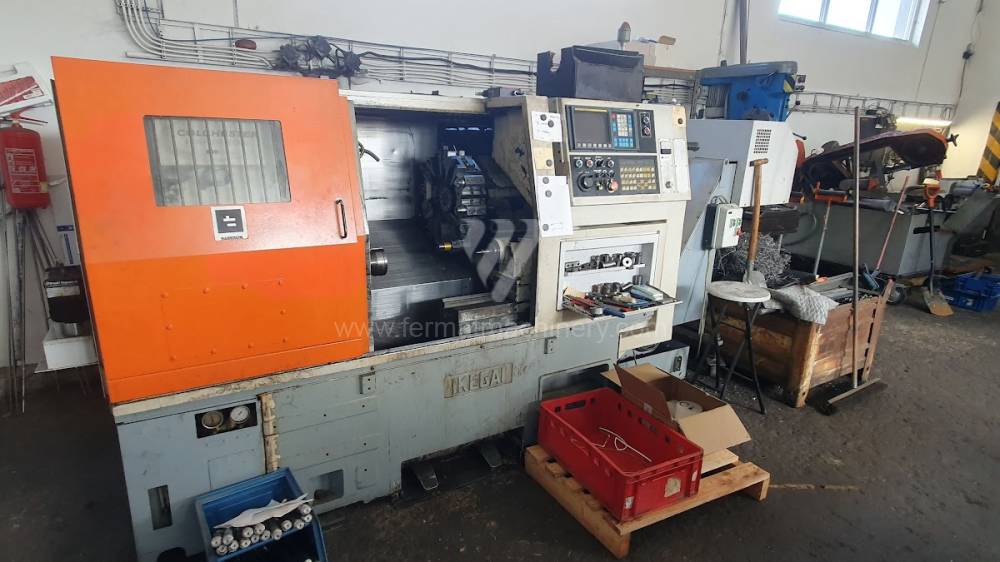
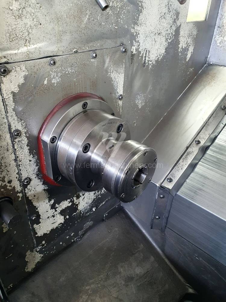
The regular lathe consists of following parts: beds, spindle, support, tailstock spindle or sliding gearbox.
Basic division of the inclination of the lathe bed:
- horizontal or sloping (inclination 45 degrees)
- sliding or linear
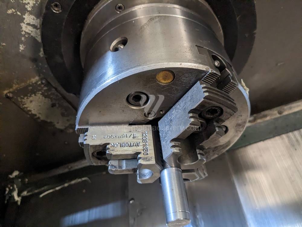
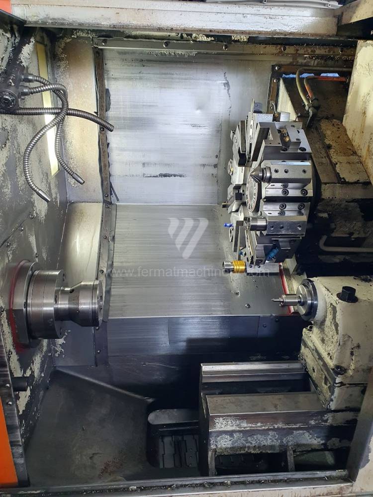
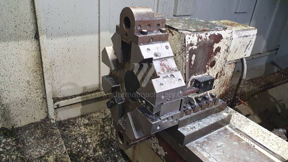
Clamping part – it is usually formed by a chuck on one side and tailstock on the other, or a chuck and second clamping part by a counter spindle.
Cutting part – formed by a cutting wedge attached to the longitudinal part - the Z axis.
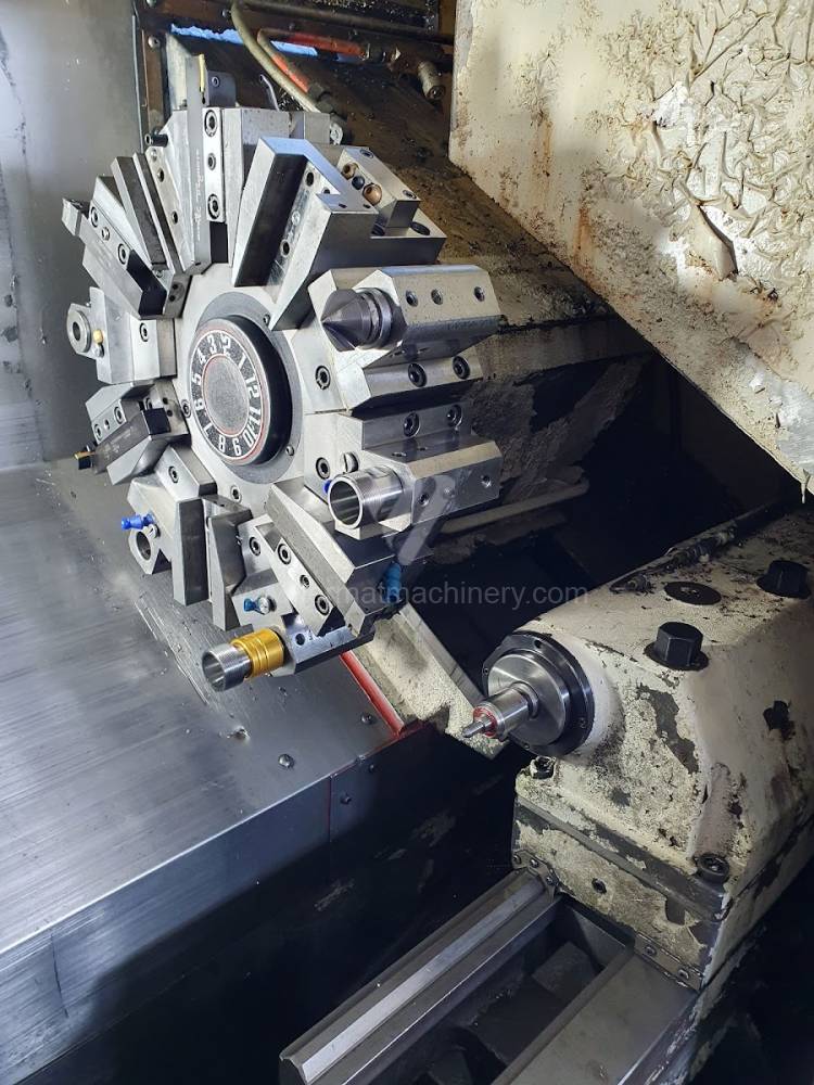
The transverse part (perpendicular to the axis of the spindle) designated as the X-axis, or the automatic tool head, also usually located on the transverse feed on the machine.
Other axes, used especially in case of CNC lathes:
- Axis C1 (indexed spindle position,
- axis C2 (indexed axis of the counter spindle)
- axis Y (Axis Y enables movement of tool perpendicular to axis Z and machining with live tools)
- axis B (indexed support axis)
The machine can be erupted with a measuring tool probe (automatically or manually foldable).