
 Français
  L'italiano
  Magyar
  Deutsch
  Polski
  Română
  Русский
  Español
  Čeština
1234 List Grid
1234Lathes CNC - diameter up to 800 mm
| Name of a product | Inventory number | Producer | YOM | Parameters | ||
|---|---|---|---|---|---|---|
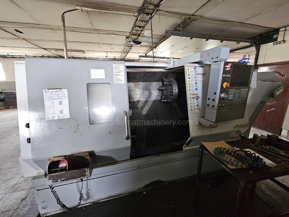 |
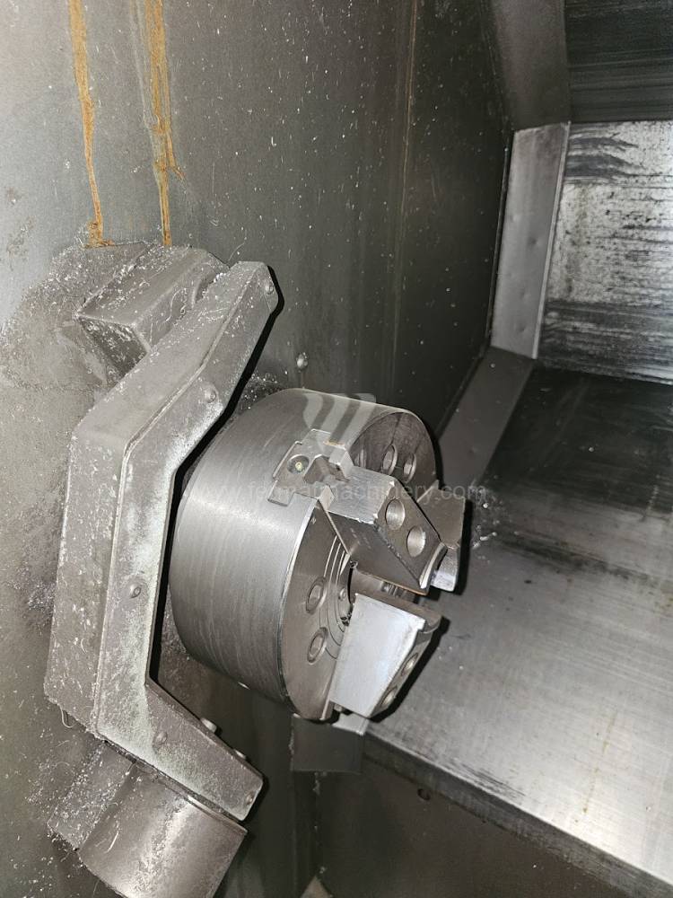
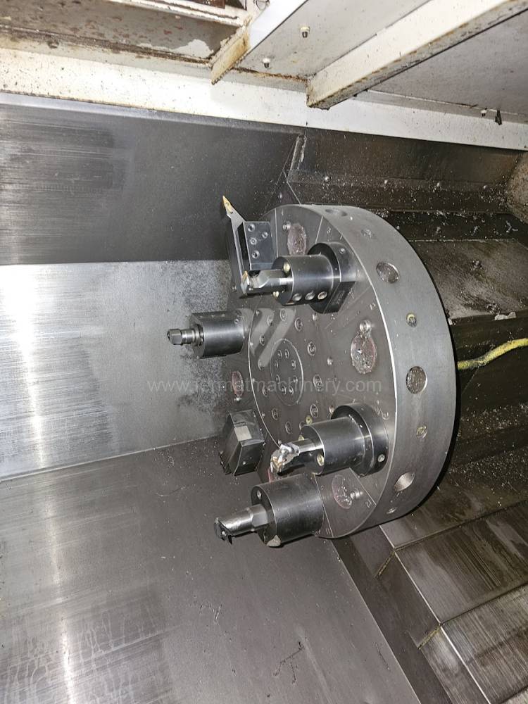
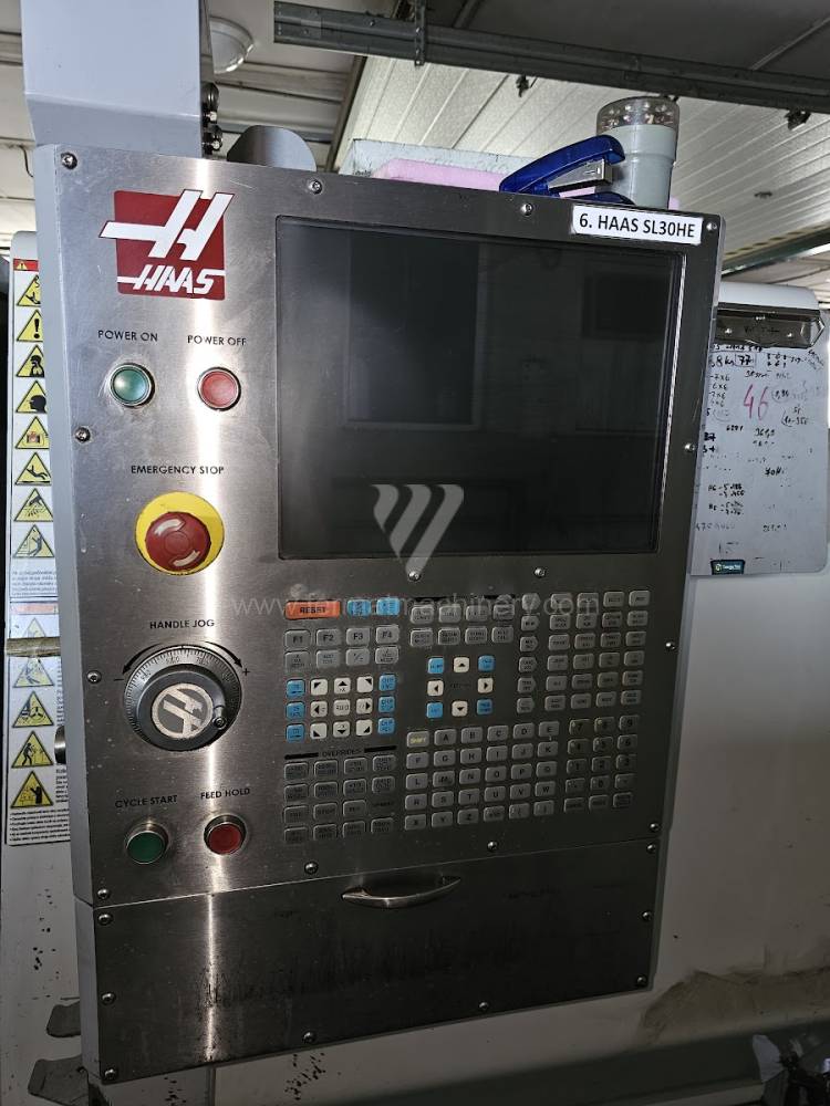
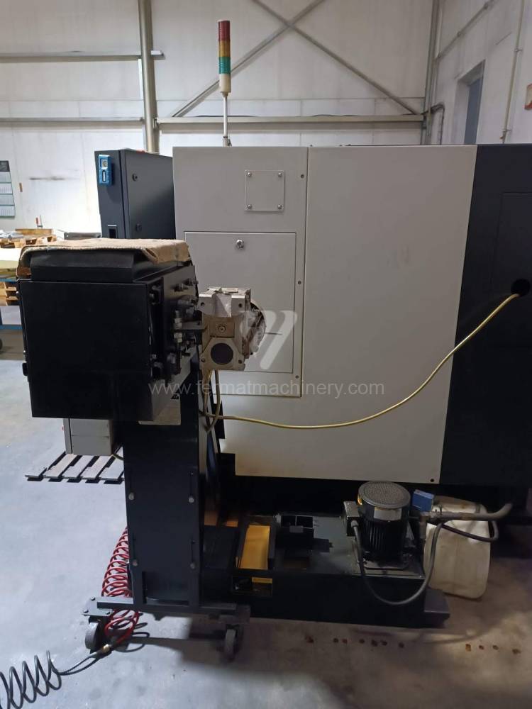
SL-30 THE |
241695 | Haas Automation | 2007 | Control system Haas: Turn table diameter: 350 mm Turning lenght: 860 mm Sloping bed: YES Spindle bore: 76 mm Turret head: YES |
|
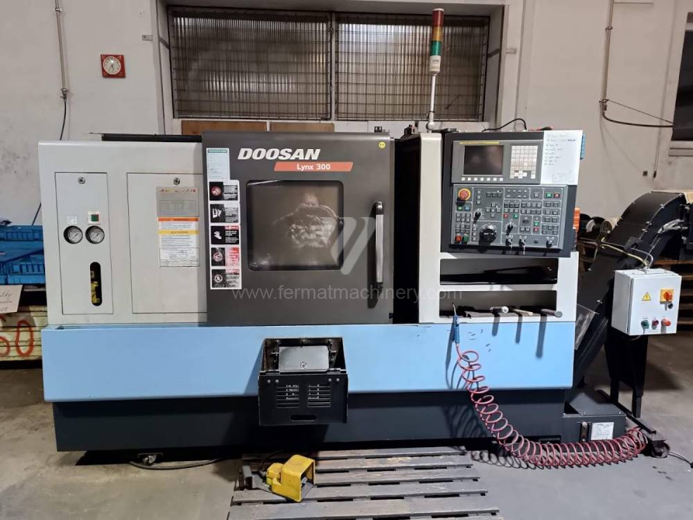 |
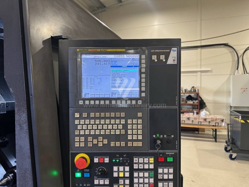
LYNX 300 |
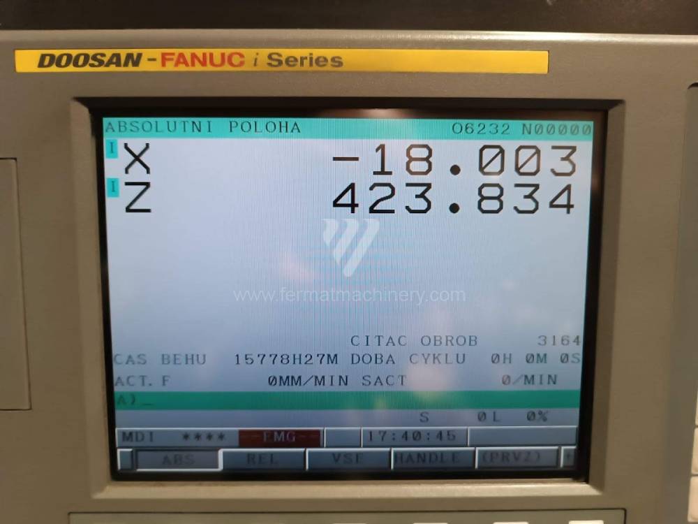
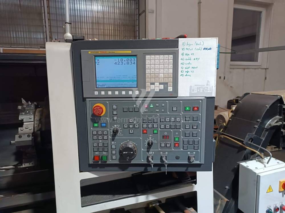
231916 | Doosan | 2011 | Control system Fanuc: i Series Turn table diameter: 450 mm Turning lenght: 750 mm Sloping bed: YES Spindle bore: 76 mm Turret head: YES |
|
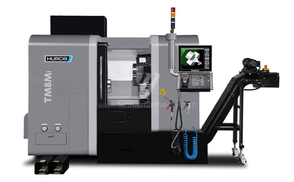 |
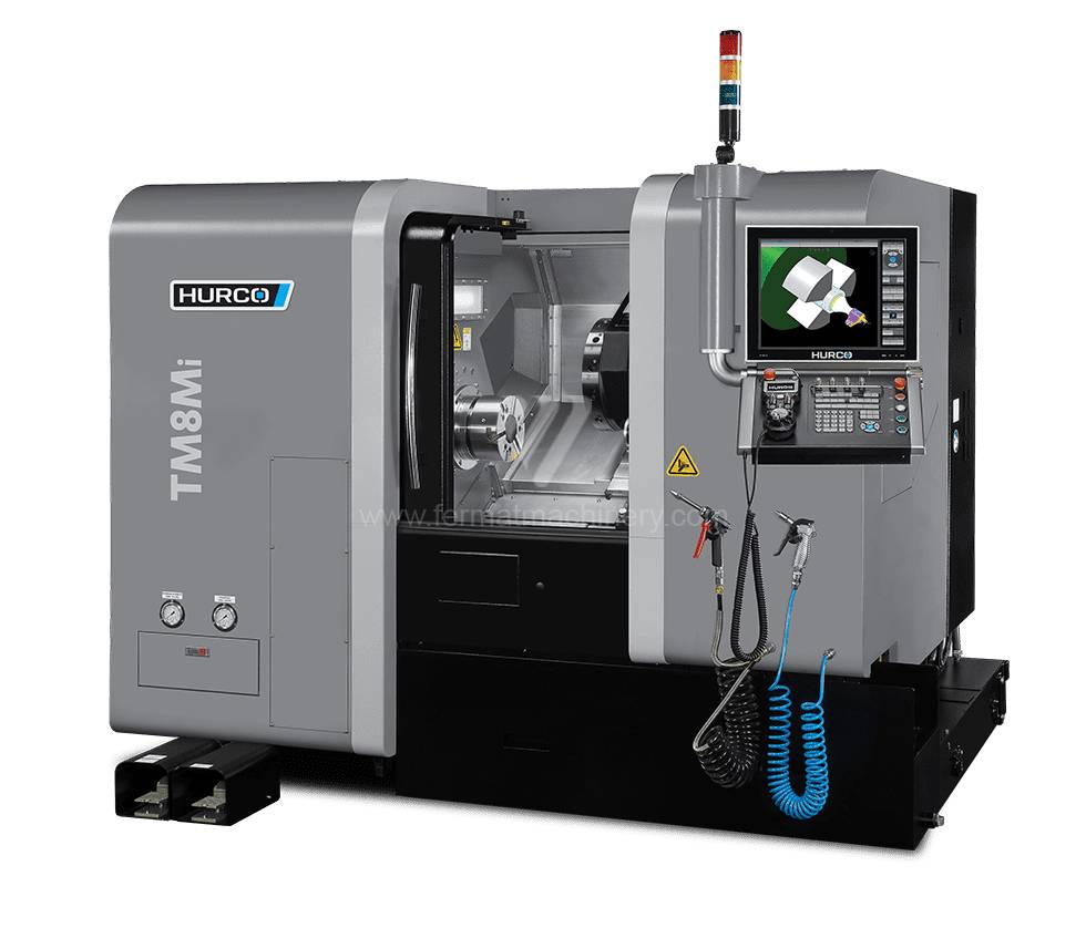
TM 8 MI |
251923 | HURCO | 2022 | Control system Hurco: Winmax Turn table diameter: 256 mm Turning lenght: 455 mm Sloping bed: YES Spindle bore: 32 mm Turret head: YES |
|
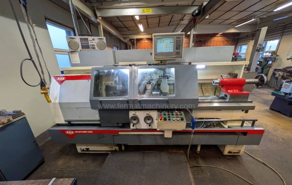 |
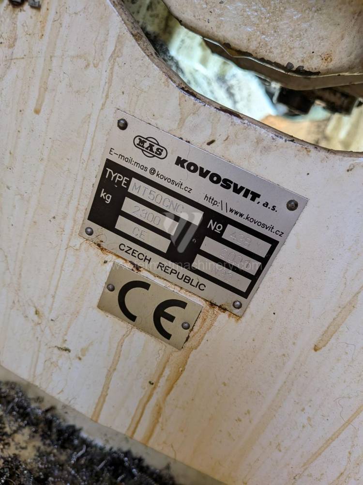
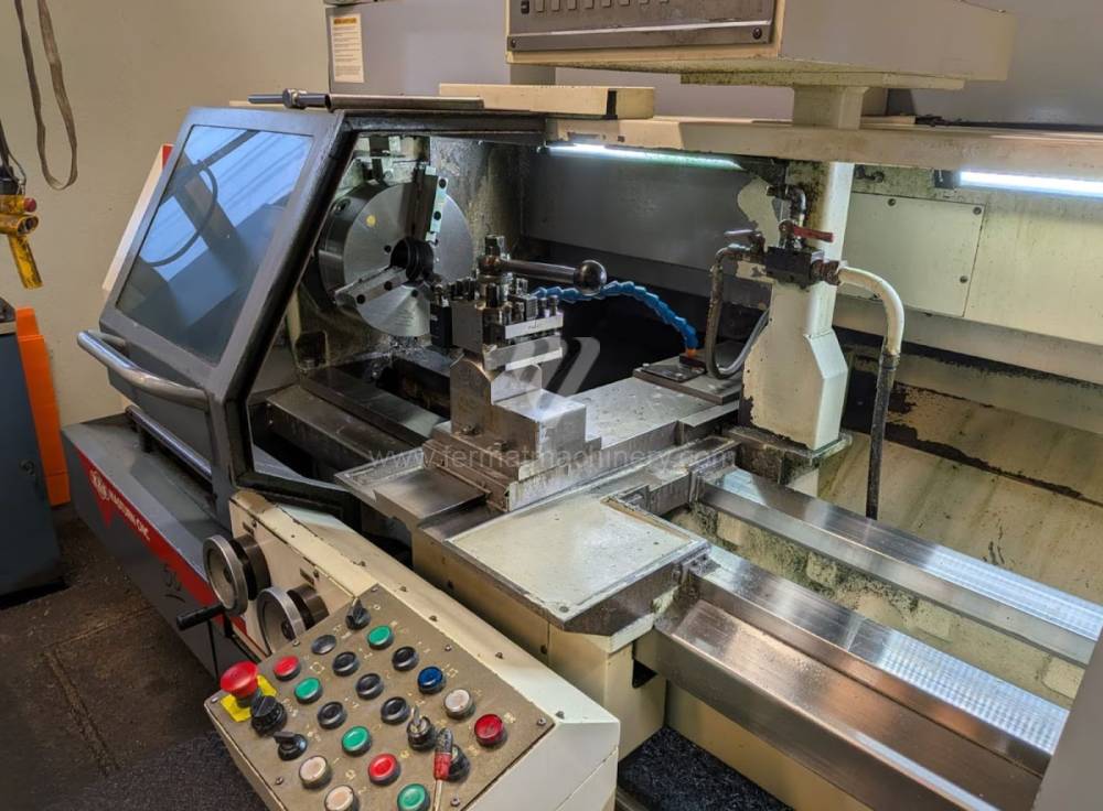
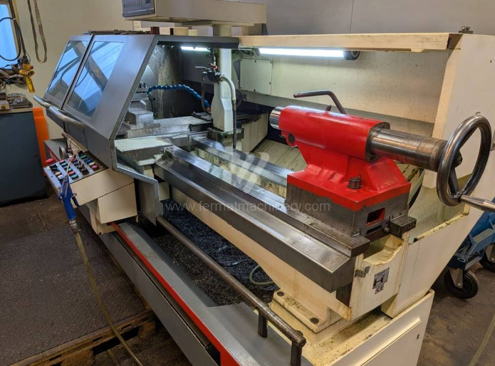
Masturn MT 50/1500 |
252014 | KOVOSVIT MAS, a.s. | 2001 | Control system Heidenhain: Manual Plus 4110 Turn table diameter: 500 mm Turning lenght: 1500 mm Sloping bed: NO Spindle bore: 82 mm Turret head: NO |
|
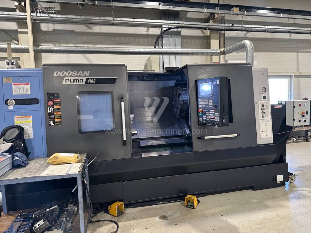 |
PUMA 4100A |
251162 | Doosan | 2018 | Control system Fanuc: i Series Turn table diameter: 790 mm Turning lenght: 1074 mm Sloping bed: YES Spindle bore: 102 mm Turret head: YES |
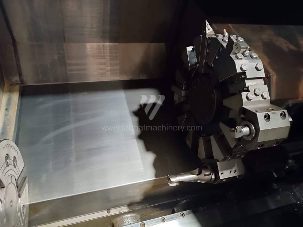
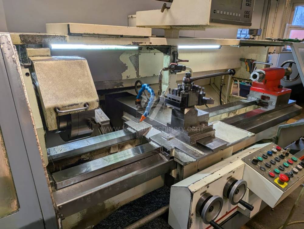
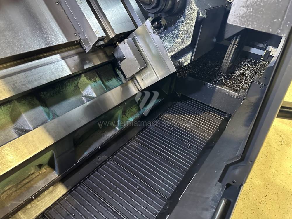
The regular lathe consists of following parts: beds, spindle, support, tailstock spindle or sliding gearbox.
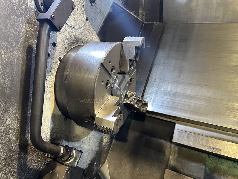
Basic division of the inclination of the lathe bed:
- horizontal or sloping (inclination 45 degrees)
- sliding or linear
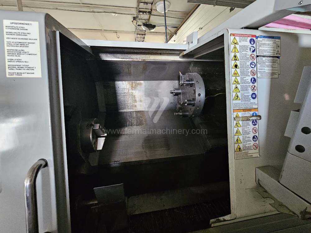
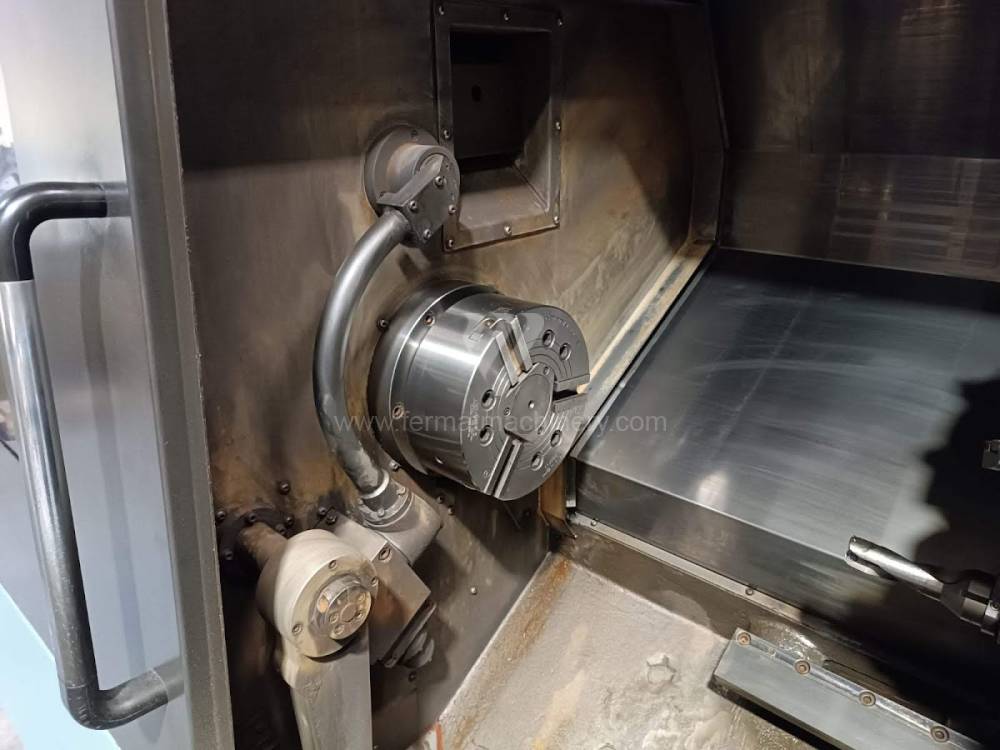
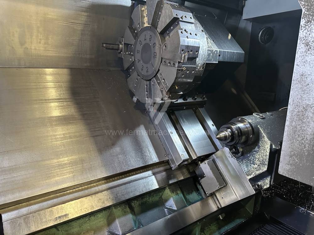
Clamping part – it is usually formed by a chuck on one side and tailstock on the other, or a chuck and second clamping part by a counter spindle.
Cutting part – formed by a cutting wedge attached to the longitudinal part - the Z axis.
The transverse part (perpendicular to the axis of the spindle) designated as the X-axis, or the automatic tool head, also usually located on the transverse feed on the machine.
Other axes, used especially in case of CNC lathes:
- Axis C1 (indexed spindle position,
- axis C2 (indexed axis of the counter spindle)
- axis Y (Axis Y enables movement of tool perpendicular to axis Z and machining with live tools)
- axis B (indexed support axis)
The machine can be erupted with a measuring tool probe (automatically or manually foldable).